This modified GoPro utilises a module inserted within the camera body to add some necessary functionality for remote use.
Here, we were taking the 1080p HDMI camera feed to recorders located 20 metres from the camera and needed to power up the camera from 12V batteries. The camera was put in a place for a long term natural history project. The problem was that there was no way to switch on the camera once power was interrupted. This occur’s when changing batteries (no UPS system in place) and there was no way to reach the camera to press the buttons.
The earlier GoPro cameras could be Powered On via the 30-pin connector which was a very simple way to remote Power On using a single capacitor on a 30-pin plug or using an external wired switch. However, the Hero4 is a very different device.
A small microprocessor design was constructed and installed within the GoPro to enable programmed functions to switch the mode, tag(wireless) and shutter buttons.
Using this to control the camera is very simple. With the camera powered by battery or an external supply, the user switches off the camera and then holds down the Shutter button for 5 seconds ( must have the “Quick Capture” feature switched off ). The Green Led flashes one long flash to disable Auto Power On or a series of quick flashes to enable Auto Power On.
The camera remembers the Auto Power On mode last selected even if the camera has not been used, indefinitely, until the user desires to change the mode.
The modes currently implemented are:
No Auto On function – long green LED flash – The camera acts without any effect of the new circuit.
Auto Power On – a series of fast green LED flashes – The camera will always turn on when it receives power or a charged battery is inserted.
Auto Power On and Auto WiFi On– two green LED flashes – as above plus WiFi On.
Auto Power On, Auto WiFi On and Record On – three green LED flashes – as above plus start recording.
Other features:
The Hero 4 is subject to shutdown if the temperature of the camera exceeds a certain value (in the higher 70deg C range in my case). This is fully described in the GoPro user manual.
In our case this overheating shutdown occurred when 4k was in use and with 1080p HDMI output and a voltage regulator was installed in the case. This was unfortunate for us, not helped by some exceptional sunny days.
To offset temperature shutdowns the modified system will attempt to restart the GoPro after 15 minutes with the aim of resuming operation. This is particularly useful where the heat buildup is due to external causes such as direct sunlight etc. The system could also stop and restart recordings on a regular basis to ensure recording are completed as any sudden power failure is likely to corrupt the current recording. A micro UPS on the power supply would help here.
Putting it All Together (added Aug 2016)
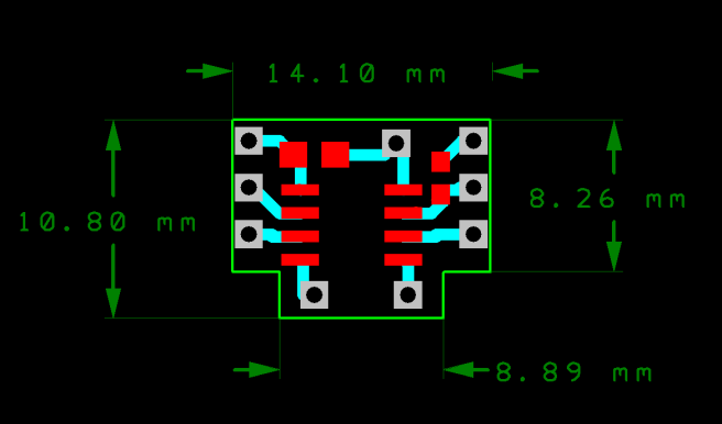
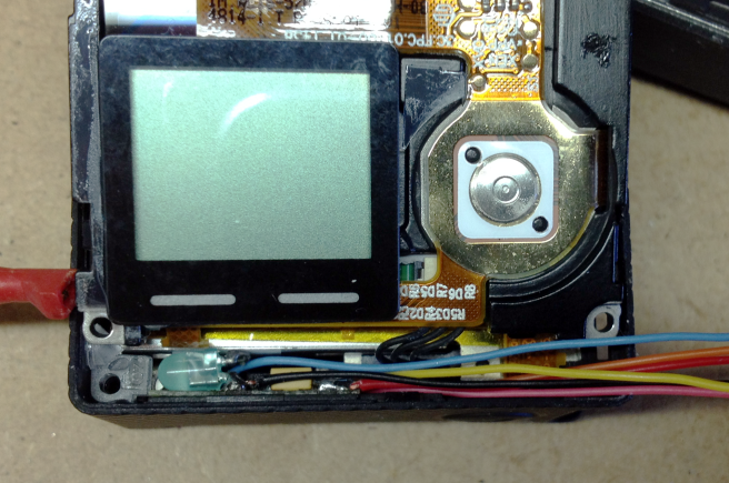
The space in the Hero 4 to fit a circuit is quite small. However, at one side there is enough space to fit a board (in this case 14mm x 11mm by 2mm) and the space is conveniently close to the top red LED light pipe which allows the new green LED to use the same indicator, effectively.
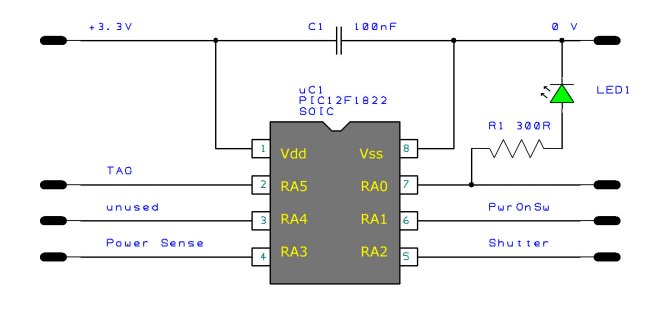
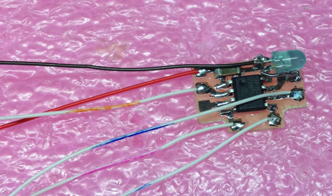
The circuit is very simple in the number of components used. It consists of a PIC microprocessor PIC12F1822 surface mounted on a 0.4mm printed circuit board (pcb) together with a Green LED, a resistor and a capacitor.
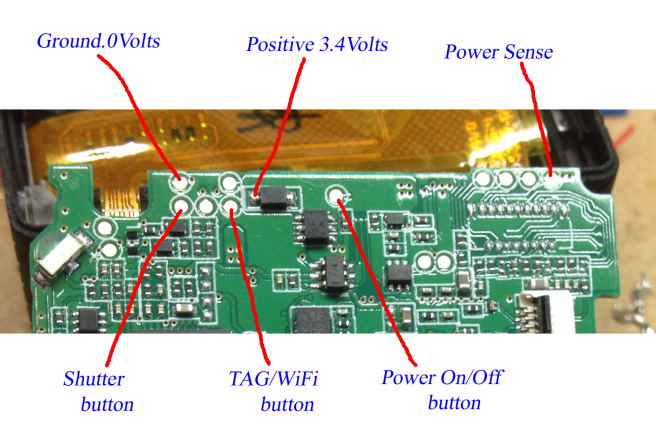
The Hero 4 has test pads on the main circuit board for each of the external switches and these facilitate the connection of fine wires to the pcb.
The PIC microprocessor is a miniature computer which is programmed to preform many tasks. The program in this case checks for changes in the power supply to an internal circuit and the user pressing the Shutter button. Depending on its previous state it will decide what action if any to preform. The PIC is capable of storing in memory the last user settings and will retain these for life or until the user decides to change a setting.
If you are familiar with microprocessors you will have noticed there is no power regulation circuit, external crystal or pull-up resistors. This is because the 5V version of the PIC is quite happy working a lower voltages provided high speed is not required. The clock source is internal (factory calibrated) and pull-up’s are provided by the GoPro circuits.
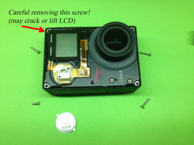
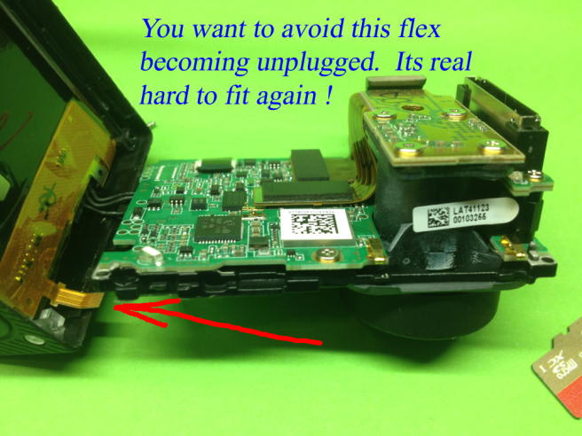
Fitting and connecting the circuit and wires is the most difficult part. The GoPro is disassembled taking care not to damage the LCD display when removing the corner screw nearest to it and try to keep the small flex connector near the WiFi button from being pulled out. Its not a serious thing if it is pulled, however it is difficult to get it back in place again, requiring some dexterity.
Auto-On Circuit (note: LED polarity was incorrect in previous schematic)
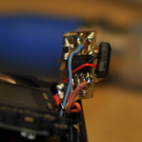
The circuit was etched on 0.4mm single sided printed circuit board and the wires soldered in place. The circuit is held in place with a small piece of double-sided tape and pressed in place. The on-board LED facing the light-pipe.
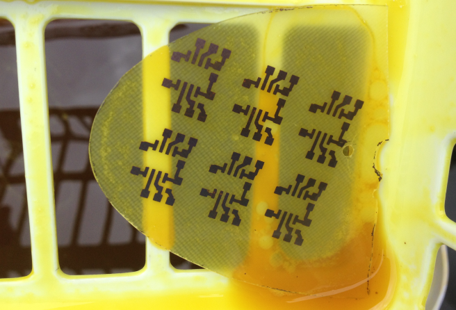
The PCB outline with pads and tracks.
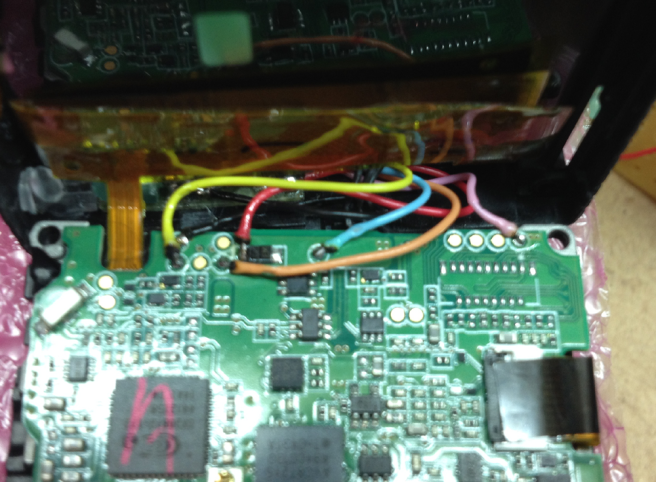
The cables are approx 20mm and are fed up to the main board where they are soldered to test points and to one end of a diode. this requires good and steady soldering skill and tweezers.
Exploring the Camera
Opening your camera and modifying things is done at your own risk. Search out videos and blogs to discover and learn from others. That’s my advice anyway.
The flex circuit I warn about is shown here (unplugged). The problem is that the connector is located under the board and the flex is exceptionally short. High quality tweezers and dexterity (I keep mentioning this) is required to refit it. It is a simple push fit, so dont be too hard on your self if it disconnects !
The pad locations are shown below
Circuit Works
PCB ‘s were etched and cut out to the required dimensions to fit the space. The components fitted and wires attached. The working circuit was then programmed and was ready to be tested and fitted.
Etching printed circuitCutout to size, components soldered and wires connected. The 3mm LED can be replaced with an edge mounted SMD 1206 type, Farnell 221-7984A snug fitWires soldered to GoPro pads
Routing the wire within the space. The pads and the diode should first be heated and solder applied. The wire ends should be soldered and clipped short (1.5 mm max) and the wires laid out so that they are not crossing each other so as to maintain the same height as the PCB components. With the help of a fine tweezers, the wires can then be soldered to the pads.
Assembling the camera, the wires can be tucked into the side space beside the new circuit. Check the flex connectors are all secure and close over the upper camera part and secure the four screws (the shorter one fits in the corner nearest the front Power/Mode button). This part should fit back in place with out forcing it. If not, open again and check the wires leave the pads cleanly and are routed away to the sides without crossing, and retry.
Write a program
The program manages the timing, in/out ports and memory. When power is applied, the device checks EEPROM memory to find the current function mode and senses the shutter button state. For example, a port will act as an input waiting for a button press or change to an output if it needs to activate a button press. The processor mimics the same timing a user keep’s a button pressed to achieve the required actions. With power applied the processor also monitors the camera on/off state. If the user has Auto-On mode active and the camera is turned off or a high temperature shutdown occurs, the processor will attempt to switch on the camera again after a 15 minute interval. This is not to confuse a casual user who believes they have switched off the camera, but to help in instances where a high temp event occurs, 15 minutes being required for the camera to cool down and hopefully conditions moderate for the better (camera heating in direct sun).
Program flow to be added next…
Hex file for the PIC12F1822 is here its name GoProSwitchOn_12F1822.HEX Must use the 5V PIC. It is programmed in C using WIZ-C from www.fored.co.uk and can easily be modified to suit others. Following is best used as a guide only, however it works just fine with WIZ-C and its library’s. A sleep function would also be a good idea to add to save power when not in use. Never posted code before so please excuse this attempt.
// GoProSwitchOn_12F1822_user.c   f.duffy 2015

#__config 0x8007,0x09A4 // 0000 1001 1010 0100 clock out disabled MCLR disabled
#__config 0x8008,0x1CFF // 0001 1100 1111 1111

void flashLedLong();
void flashLed1();
void flashLed2();
void flashLed3();
void flashLed4();
void flashLed8();

BYTE EnableAutoPowerOn;
BYTE EnableAutoWiFiOn;
BYTE EnableAutoRecordOn;
BYTE FirstTime;
BYTE SwitchedOn;
BYTE WiFiOn;
BYTE RecordOn;
BYTE CheckWiFiProg;
BYTE CheckRecordProg;
BYTE ReleaseWait;
BYTE UserSwitchedOff;
BYTE CameraStartUp;
BYTE CaughtSpace;
BYTE WaitForPress;

int ShutterCount;
int CountRelease;
int CountPress;

char Minutes;
BYTE ReStart;

void UserInterrupt()
{
// Insert any user interrupt code here

#asmline SETPCLATH UserIntReturn,-1 ; SETPCLATH for interrupt routine
#asmline goto UserIntReturn ; Assembler - go back to interrupt routine
}

void UserInitialise()
{

// Using the reset default of 500kHz but leave this in place
// in case we want to change 0111 = 500kHz

OSCCON|=(1<<IRCF0);
OSCCON|=(1<<IRCF1);
OSCCON|=(1<<IRCF2);
OSCCON&=~(1<<IRCF3);
OSCCON|=(1<<SCS1); // Internal osc block, config word will set also if SCS0-1 are 0

// switch all output pin configurations to high impeadance - Inputs .
TRISA=0x3e; // All (except LED) as inputs 0011 1110

// WIZ-C weak pullup element does not set these correctly - so set here instead
// For use in the gopro we dont want to pull up to the 3.7 battery volt supply
// so we disable pullups - can enabled here is for bench testing only
//OPTION_REG&=~(1<<NOT_WPUEN); // bit7 - clear if enabled
//WPUA=0x3E; // B'00111110' 1 - is enabled
WPUA=0x00; // No Pullups when in circuit - All High Z and ouputs only pulling low

ReadEEData(1); // EEDAT for 12F1822, EEDATA for 12F675
if(EEDAT==0xff) WriteEEData(1,0x00); // preset to 0 if not previously used

ReadEEData(2); // EEDAT for 12F1822, EEDATA for 12F675
if(EEDAT==0xff) WriteEEData(2,0x00); // preset to 0 if not previously used

ReadEEData(3); // EEDAT for 12F1822, EEDATA for 12F675
if(EEDAT==0xff) WriteEEData(3,0x00); // preset to 0 if not previously used

ReadEEData(1);
if(EEDAT==1) EnableAutoPowerOn = 1; else EnableAutoPowerOn = 0;

ReadEEData(2);
if(EEDAT==1) EnableAutoWiFiOn = 1; else EnableAutoWiFiOn = 0;

ReadEEData(3);
if(EEDAT==1) EnableAutoRecordOn = 1; else EnableAutoRecordOn = 0;

FirstTime=1;
}

/*******************************************************************/
void UserLoop()
{

// Just flash the LED when the Battery or External power is applied.

if(FirstTime)
 {
  FirstTime=0;
  if(EnableAutoPowerOn) flashLed1();
  if(EnableAutoWiFiOn) flashLed1();
  if(EnableAutoRecordOn) flashLed1();
  if(!EnableAutoPowerOn && !EnableAutoWiFiOn && !EnableAutoRecordOn) flashLedLong();
  Wait(1000);
 }

// Reset Shutter Button hold down count when not pressed
if(Shutter) ShutterCount=0;

// State where power has been off - we turn it on
// This is not good if user has switched it off for some reason
// so we need to detect when user switches off and set a flag
// This flag will be forgotten only when power fails - battery flat or change
if(EnableAutoPowerOn)
 {
  if(!PwrSense && !SwitchedOn)
   {
    TRISA&=~0x02; // output PwrOnSw
    PwrOnSw = 0;
    Wait(500); // 1/2 sec
    PwrOnSw = 1;
    TRISA|=0x02; // back to Hi-Z

   flashLed1();
   Wait(5000);
   SwitchedOn=1;
  }
 }

if(EnableAutoWiFiOn)
 {
  if(SwitchedOn && !WiFiOn)
   {
    TRISA&=~0x20; // output TAG b5
    TAG = 0;
    Wait(3000); // 3 Sec minimum
    TAG = 1;
    TRISA|=0x20; // back to Hi-Z
    flashLed2();
    Wait(2000);
    WiFiOn=1;
   }
 }

if(EnableAutoRecordOn)
 {
  if(SwitchedOn && WiFiOn && !RecordOn)
   {
    TRISA&=~0x04; // output Shutter
    Shutter = 0;
    Wait(100); // 100mSec
    Shutter = 1;
    TRISA|=0x04; // back to Hi-Z
    flashLed3();
    RecordOn=1;
   }
 }

if(ReStart)
 {
  ReStart=0;
  Minutes=0;
  TRISA&=~(1<<PwrOnSw); // output
  PwrOnSw = 0;
  Wait(500); // 1/2 sec
  PwrOnSw = 1;
  TRISA|=(1<<PwrOnSw); // back to Hi-Z   flashLed2();   SwitchedOn=1;  } // State when user has switched off camera - state when user may use the Shutter // button to enable or disable Automatic Turn On if(!PwrSense && !Shutter && !CameraStartUp) CameraStartUp=1; if(!Shutter && CameraStartUp)  {   ShutterCount++;   if (ShutterCount>=4000) // Approx 4 seconds
   {
    ShutterCount=0;
    CameraStartUp=0;
    if(EnableAutoPowerOn)
     {
      EnableAutoPowerOn=0;
      SwitchedOn=0;
      WriteEEData(1,0x00); // Clear EEPROM
      Wait(5);
      WriteEEData(2,0x00);
      Wait(5);
      WriteEEData(3,0x00);
      flashLedLong();
     }
    else
     {
      EnableAutoPowerOn=1;
      SwitchedOn=1;
      WriteEEData(1,0x01);
      flashLed8();
      CheckWiFiProg=1; // Check if AutoWiFi is going to be set
      ReleaseWait=1; // Check if finger has been released from shutter
     }
   }
 }

if(CheckWiFiProg)
// Want to ensure the finger was lifted and wait period has not elapsed
 {
  CountRelease++;
  if(CountRelease>=0x2500) // only give 2 1/2 seconds to press for Wifi
   {
    CountRelease=0;
    CheckWiFiProg=0;
    ReleaseWait=0;
    WaitForPress=0;
   }
  else WaitForPress=1;
 }

if(CheckRecordProg)
// Want to ensure the finger was lifted and wait period has not elapsed
 {
  CountRelease++;
  if(CountRelease>=0x2500) // only give 2 1/2 seconds to press for Record
   {
    CountRelease=0;
    CheckRecordProg=0;
    ReleaseWait=0;
    WaitForPress=0;
   }
  else WaitForPress=1;
 }

if(CheckWiFiProg && Shutter) CaughtSpace=1; // finger lift
if(CheckRecordProg && Shutter) CaughtSpace=1; // finger lift

// if Shutter pressed again
if(WaitForPress && CaughtSpace && !Shutter && CheckWiFiProg)
 {
  CountPress++;
  if(CountPress>=500)
   {
    CountPress=0;
    WaitForPress=0;
    CaughtSpace=0;
    CheckWiFiProg=0;
    ReleaseWait=0;
    CountRelease=0;

    EnableAutoWiFiOn=1;
    WiFiOn=1;
    WriteEEData(2,0x01);
    flashLed2();
    CheckRecordProg=1; // Check if AutoRecord is going to be set
    ReleaseWait=1; // Check if finger has been released from shutter
   }
 }
// if Shutter pressed again
if(WaitForPress && CaughtSpace && !Shutter && CheckRecordProg)
 {
  CountPress++;
  if(CountPress>=500)
   {
    CountPress=0;
    WaitForPress=0;
    CaughtSpace=0;
    CheckRecordProg=0;
    ReleaseWait=0;
    CountRelease=0;

    EnableAutoRecordOn=1;
    RecordOn=1;
    WriteEEData(3,0x01);
    flashLed3();
   }
  }
}  // End of user loop

/*****************************************************************/

void MinuteCount()
{
 if(!PwrSense & SwitchedOn)
  {
   Minutes++;
   if(Minutes>=15)
    {
     Minutes=0;
     ReStart=1;
    }
  }
 else Minutes = 0; // Reset Minutes
}

void flashLedLong()
{
 LED=1;
 Wait(1500);
 LED=0;
}

void flashLed1()
{
 LED=1; Wait(200); LED=0; Wait(200);
}

void flashLed2()
{
 LED=1; Wait(200); LED=0; Wait(200);
 LED=1; Wait(200); LED=0;
}

void flashLed3()
{
 LED=1; Wait(200); LED=0; Wait(200);
 LED=1; Wait(200); LED=0; Wait(200);
 LED=1; Wait(200); LED=0;
}

void flashLed4()
{
 LED=1; Wait(200); LED=0; Wait(200);
 LED=1; Wait(200); LED=0; Wait(200);
 LED=1; Wait(200); LED=0; Wait(200);
 LED=1; Wait(200); LED=0;
}

void flashLed8()
{
 LED=1; Wait(50); LED=0; Wait(50);
 LED=1; Wait(50); LED=0; Wait(50);
 LED=1; Wait(50); LED=0; Wait(50);
 LED=1; Wait(50); LED=0; Wait(50);
 LED=1; Wait(50); LED=0; Wait(50);
 LED=1; Wait(50); LED=0; Wait(50);
 LED=1; Wait(50); LED=0; Wait(100);
LED=1; Wait(50); LED=0;
}